 |
| Sieve Shaker |
Sieving is the most widely used technique in the pharmaceutical industry for particle size analysis. The particles are classified based on their size, independent of any other particle characteristics such as density and surface properties. Micromesh sieves are used to classify particles of size range 5 - 20 µm, while particles of size range 20 -125 µm are classified in the standard woven wire sieves. Coarse particles (>125 µm) are classified in punched plate sieves. Punched plate sieves are commonly used in industrial applications where the openings are circular or rectangular. The sieves can take different configurations.
Principle of Sieve Shaker:
The principle of sieve shaker is based upon vibration,
agitation, or gyration. The efficiency of sieving by sieve shaker depends on
the particles size distribution, sieve load, the method of sieve shaking, the
dimension and shape of the particle, and the ratio of the open area of sieve to
total area. The sieving operation can be affected by the friability and
cohesiveness of the powder. During sieving, the sample is subjected to
horizontal or vertical movement by the chosen method. This causes a relative
movement between the particles and the sieve. Depending on the size the
individual particles either pass through the sieve mesh or are retained on the
sieve surface. The likelihood of a particle passing through the sieve mesh is
determined by the ratio of the particle size to the sieve openings, the
orientation of the particle, and the number of encounters between the particle
and the mesh openings. Thus sieving depends on the sieve movement and the
sieving time.
Construction of Sieve Shaker:
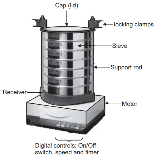
The sieve shaker consists basically of a cradle for
holding the sieves, a power unit, and a base. The cradle consists of a platform
fastened to the lower ends of two vertical support rods, Fig.1. The upper ends
of which are shock-mounted to horizontal support that is free to pivot about
its mounting. A sieve holder, a retaining ring, and nuts on the vertical
support rods hold the top bar firmly against the nest of sieves. The standard
sieves of different sieve numbers are used.
Working of Sieve Shaker:
The sieving by sieve shaker is conducted using up to
11 sieves stacked with progressively larger aperture openings towards the top.
The sample is placed on the top sieve. A closed pan (receiver) is placed at the
bottom. There are several methods for shaking the sieves by mechanical or
ultrasonic means. The residues in each sieve are recorded and expressed in
percentage as cumulative values against the nominal sieve aperture values. The
common methods of sieving are machine, wet, hand, and air-jet sieving.
Wet-sieving is recommended for material originally suspended in a liquid and is
necessary for powders that form aggregates when dry-sieved. In such sieving,
the stack of sieves is filled with liquid and the sample is fed to the top sieve.
Sieving is accomplished by rinsing, vibration, reciprocating action, vacuum,
ultrasonication, or a combination of these.
(a) Manual and mechanical sieving:
Today, manual sieving is only used where no electricity supply is available,
for example, for rapid on-site random checking for oversize and undersize. It
is only used for orientation purposes. In contrast, sieve analyses in the
laboratory and for quality assurance are carried out with sieve shakers. Modern
sieve shakers are characterized by the fact that their mechanical parameters,
such as sieving time and amplitude or speed, are carried out with exact
reproducibility. In the laboratory, a differentiation is made between
horizontal sieve shakers and throw-action sieve shakers.
(b) Throw-action sieving:
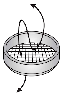
Throw-action sieve shakers are also known as vibratory sieve shakers. An
electromagnetic drive sets a spring-mass system in motion and transfers the
oscillations to the sieve stack. The sample is subjected to a 3-dimensional
movement and is distributed uniformly across the whole area of the sieve, Fig.2.
The amplitude can normally be set continuously in the range from 0-2 mm or 0-3
mm. Modern instruments enable the required amplitude to be entered digitally.
During the sieving process, a built-in measuring system and control unit
performs a continuous comparison between the set and actual amplitude values.
This provides the optimal preconditions for reproducible sieving parameters.
Digital accuracy for the sieving time and the interval function is a matter of
course.
Fig.2: In Throw-Action Sieving the Sample is Subjected to a 3-Dimensional Movement
(c) Horizontal sieving:
In a horizontal sieve shaker the sieves move in horizontal circles in one
plane, Fig.3. Horizontal sieve shakers are preferably used for needle-shaped,
flat, long, or fibrous samples, as their horizontal orientation means that only
a few disorientated particles enter the mesh and the sieve is not blocked so
quickly.
The AS 400 control permits the use of test sieves with
a diameter up to 400 mm. The large sieving area makes it possible to sieve
large amounts of sample, for example as encountered in the particle size analysis
of coarse granules and aggregates. In addition, in the fine particle size range
and for obtaining single fractions, ultrasonic and air-jet sieving is used for
special applications.
Fig.3: In Horizontal Sieving the Sample Moves in Horizontal Circles
(d) Sieve set sieving:
Sieve set sieving is the process in which a set of several sieves is used
together with a collector pan. The test sieves are arranged in a stack with the
largest mesh openings at the top of the stack. The sample is placed on the top
sieve and allowed to pass through in lower sieves.
(e) Dry and wet sieving:
Most sieving processes are carried out on dry materials. However, there are
many applications in which wet sieving cannot be avoided, for example,
suspension or when a very fine sample that tends to agglomerate has to be
sieved. As in dry sieving, a sieve stack is assembled on a sieve shaker. The
sieving process is additionally supported by water from a spray nozzle located
above the uppermost sieve. The sample is placed on the uppermost sieve in the
form of a suspension. Rinsing is carried out until the sieving liquid leaving
the sieve stack outlet is no longer turbid with solid particles. In wet
sieving, the sieving liquid must not alter the physical or chemical properties
of the sample.
Optimal sieving time and amplitude or speed:
The settings for the sieving time and the optimal
amplitude or speed depending on the material to be sieved. National and
international standards, internal regulations, and standards normally provide
detailed information about product-specific sieve analyses and their associated
sieving parameters. The instruction manual for the sieve shaker should also
provide guidelines for this. If this basic information does not exist then the
sieving time and amplitude or speed must be determined experimentally. This is
done by first selecting a relatively short sieving time (for example, 5 min)
and carrying out sieving at various amplitudes or speeds to determine at which
values the largest amount of sample passes through the sieves (optimal sieving
quality).
Sieving Aids:
Sieving aids are used for very fine samples that tend
to adhere together. They are used to make the sample sievable. A
differentiation is made between mechanical sieving aids (for example, rubber
cubes, brushes, balls, chains) for eliminating molecular adhesive forces, and
additives (for example, talcum, Aerosil) for greasy, sticky, and oil-containing
products. Antistatic sprays reduce electrostatic charges whereas surfactants
reduce the surface tension in wet sieving.
A complete sieving process includes the following steps which should be performed in a precise careful manner.
- Sampling.
- Sample division (if required).
- Selection of suitable test sieves.
- Selection of sieving parameters.
- Actual sieve analysis.
- Recovery of sample material.
- Data evaluation.
- Cleaning and drying the test sieves.
Advantages of Sieve Shaker:
- Sieve shaker is simple to operate.
- It separates samples rapidly.
- It is suitable only for particle size up to 50 µm.
- Requires less area for its installation.
- Results of particle sizing are accurate and reproducible.
- The cost of the instrument is lower than other methods.
Disadvantages of Sieve Shaker:
- For materials finer than 100 mesh, dry sieving can be significantly less accurate.
- Sieve analysis assumes that all particles will be round (spherical) or nearly so but in reality, it is not the fact.
- For elongated and flat particles a sieve analysis does not yield reliable mass-based results.
- Not suitable for particles smaller than 50 µm.
- There is a possibility of further reduction in size, which can cause errors.
- Sieves could be clogged and distorted if not properly handled and maintained.
Applications of Sieve Shaker:
- A Sieve shaker is used for particle size analysis of a variety of materials.
- It is suitable for coarse material down to 150 µm.
- It can be used for wet sieve analysis where the material analyzed is not affected by the liquid - except to disperse it.
Make sure you also check our other amazing Article on : Mechanisms of Size Separation

